 日本語 /
日本語 /  English
Overview
Some IC design errors are not readily detectable with standard front-end SPICE and Verilog simulation or back-end LVS and DRC verification. These errors include leaks due to intermittent floating inputs or shorts, problems with signals crossing differing voltage domains, errors related to input and output of cutoff regions, and errors due to integrating varying IP. CVC is designed to pinpoint these types of errors and is able to verify a full design quickly. Similar tools include: Synopsys’ CustomSim Circuit Check(CCK), Mentor Graphics’ Calibre PERC, Cadence’s PVS PERC.
Merits
- Fast
70M gate design read in 5 minutes, total run time 45 minutes. (Linux RedHatE5, Intel Xeon E5-2690, 256GB). - High capacity
100M+ gate designs can be checked. - Comprehensive
All error types detected in single execution. - Error management
Errors are marked with references and classified by severity. Fewer missed errors. Easier review.
Input/Output
Input
- CDL netlist used for Calibre LVS (full chip simulation is recommended).
- Power settings (Excel): Nets are defined as power (fixed voltage), input (minimum and/or maximum and/or simulation level), or internal nets. Power may be defined as “open”.
- Device settings(Excel): Basic devices are mosfet, resistors, capacitors , diodes and bipolar transistors. These devices may be defined as switches (on/off) or fuses (on/off).
Output
- Individual device error list with connected nets.
- Error summary list with error counts by error type.
Algorithm
If you move the cursor to the figure, the explanation will be displayed.

Error types
Undefined power and devices
all power definitions must exist in netlist and all device models must be defined in the device file. Device definitions may be differentiated by parameters (e.g. L>100nm).
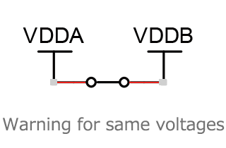
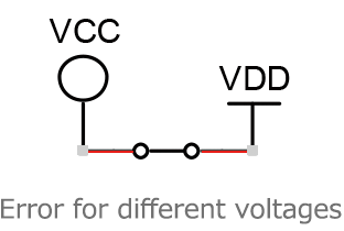
Shorts through switches
Different metal masks may be created by using metal switches (resistors or capacitors in the netlist). For normal simulation, a different netlist is required for each mask. However, both mask configurations can be verified with one netlist using CVC by changing the switch definitions in the device file. Nets shorted via switches are considered to be the same net.
Forward bias diodes
including mosfet bulk-source/drain diodes.
VBB<VSS
NMOS bulk-source is
forward biased
Output
ESD (VSS) diode may
be forward biased
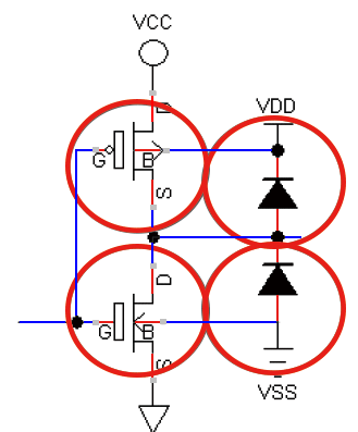
VCC>VDD
PMOS source-bulk
is forward biased
Output ESD (VDD)
diode may be
forward biased
Mosfet gate vs source
mosfets that are always on because the max gate voltage <max source voltage for pmos, or the min gate voltage> min source voltage for nmos.
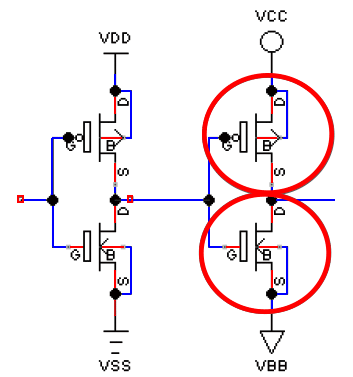
VDD<VCC
PMOS is always on
VSS>VBB
NMOS is always on
Shorts
all shorts between power signals are reported and other shorts (input, internal nets) are reported if the current exceeds a specified limit.
Mosfet undefined bulk
generally, this indicates a missing power definition.
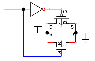
Possible leak
Mosfet error where the source and drain are connected to different power nets and the gate level is indeterminate. This is a potential intermittent error that is not readily detectible by other programs.
Short only
when input is high
Also detects
these errors
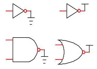
Hi-Z input
logically undriven gates.
Hi-Z input but
no leak path
therefore no error
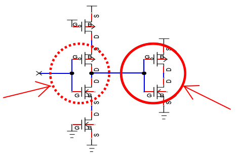
Hi-Z input
with leak path
therefore error
Overvoltage
detected if the maximum voltage difference exceeds the specified tolerance for each device/terminal combination. For mosfets, the gate-source, source-drain, source-bulk, gate-bulk checks are all possible.
Expected values
expected values can be set for minimum, maximum, and simulation voltages. An error is generated if the calculated value does not match the expected value. It is possible to expect undriven (open) nets.
License
CVC is released under the open-source GPLv3 license.
ShuhariSystem Support
Maintenance contract
There are no guarantees for software released under GPLv3. However, ShuhariSystem provides a time-based maintenance contract that covers installation support and bug fixes. Other training and requests for additional checks will be handled separately on a case-by-case basis.
Third-party verification
As with other verification tools, the settings to detect the desired errors with minimal false errors require some degree of experience. To decrease designers’ burden of learning a new tool, ShushariSystems offers an on-site third party verification service on a per chip basis.
The cost is based on the number of gates/memory size, the number of modes, and the number of requests.
Contact
ShuhariSystem, Inc.
Room 509, 3-8-33 Momochihama, Sawara-ku
Fukuoka-shi, Fukuoka-ken 814-0013 Japan
Tel: +81-92-400-4535 FAX: +81-92-881-4426
FAX 092-881-4426
URL:https://www.shuharisystem.com/ (Japanese only)
Email: support@shuharisystem.com